- Home | Pentair Food & Beverage Solutions
- Products
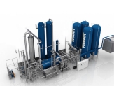
- CO2 Extraction Plants for Boiler Systems - Extraction Based Unit - EBU
High-Purity CO₂ from Boiler Systems
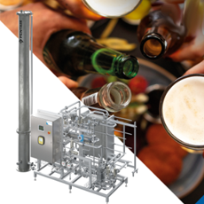
Union Engineering’s Extraction-Based Unit (EBU) captures CO₂ from boiler flue gas, whether fired with diesel, heavy fuel oil, kerosene, natural gas, LPG, or LNG, delivering high-purity CO₂ for beverage-grade applications.
Designed for soft drink bottlers and other industries, EBU technology helps you achieve CO₂ self-sufficiency, reduce operational costs, and minimize environmental impact—all while meeting the strictest quality standards.
Why Choose the EBU
- Up to 45% energy savings versus traditional combustion‑based CO₂ plants.
- Supply security: Reduce dependence on external CO₂ markets and price volatility.
- Sustainability: Turn flue gas into a valuable ingredient and cut site emissions.
- Food‑grade quality: Designed to comply with ISBT and EIGA specifications.
Performance & Quality
- Purity: ≥ 99.999% (v/v) beverage‑grade CO₂.
- Oxygen: ≤ 5 ppm (v/v).
- Energy efficiency: Up to 45% savings, especially where steam and flue gas are continuously available.
-
Functional Description
-
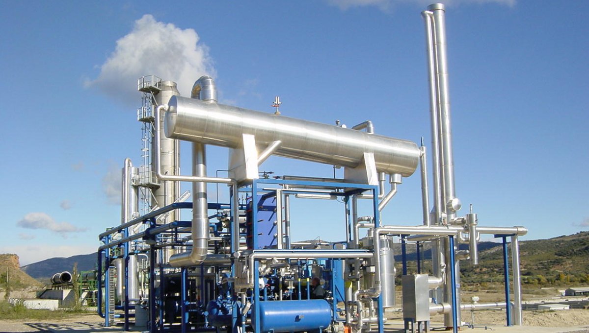
The Extraction-Based Unit (EBU) converts boiler flue gas into ultra-pure, beverage-grade CO₂ through a series of controlled steps:
1. Flue Gas Conditioning
Source: Flue gas from boilers fired with diesel, heavy fuel oil, kerosene, natural gas, LPG, or LNG.
Cooling & Scrubbing: The gas is cooled to condense water and scrubbed to remove impurities.
SO₂ Removal: Sodium carbonate (soda ash) is automatically dosed via pH control to neutralize sulfur compounds.
2. CO₂ Absorption
The conditioned flue gas enters an absorber column, flowing counter-current to a 9% MEA (monoethanolamine) solution.
The MEA solution chemically binds to CO₂ from the flue gas, creating a rich solution while minimizing corrosion risk.
3. Contaminant Removal (NOxFlash)
The rich MEA solution passes through the NOxFlash column, where oxygen, nitrogen, and NOx are removed without using potassium permanganate.
This patented process also reduces benzene and other hydrocarbons, ensuring product safety.
4. CO₂ Stripping
Heat from a steam-driven reboiler releases CO₂ from the MEA solution.
The lean MEA is cooled and recycled back to the absorber for continuous operation.
5. Gas Polishing & Purification
After-scrubber: Removes any MEA carry-over.
Compression: CO₂ is compressed in two stages to ~15–18 barg.
Drying: Achieves a dew point of −60 °C (≤10 ppm v/v H₂O).
Activated Carbon Filter: Eliminates trace odors and acetaldehyde.
6. Final Purification (PUR-D)
CO₂ passes through a distillation column to remove non-condensable gases.
Result: O₂ ≤ 5 ppm (v/v) and CO₂ purity ≥ 99.999% (v/v).
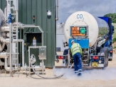
7. Liquefaction & Storage
CO₂ is condensed at −27 °C to −21 °C and stored in insulated tanks at ~15–18 barg.
A refrigeration unit maintains temperature and pressure, even during idle periods.
-
Fields of Application
-
Ideal for:
- Soft drink bottlers.
- Breweries and distilleries.
- Industrial plants with boiler systems.
-
Typical Plant Capacities
-
CO2 extraction plant standard sizes (measured as liquid food-grade CO2 produced);
- 145 kg/h
- 285 kg/h.
- 500 kg/h.
- 1000 kg/h.
- 1500 kg/h.
- 2000 kg/h.
Other sizes are available on request.
DOWNLOADS
| Title | Download PDF | |
| Product leaflet | Union Engineering Extraction Based Unit - EBU | Download |
| Technical documentation | Looking for operating instructions, installation manual, spare part list, etc.? | Please, send us your request |
RELATED PRODUCTS
PENTAIR UNION ENGINEERING ADVANCED AMINE TECHNOLOGY
CO2 capture technology for low-CO2 concentration sources
The analysis of both commercial and recovered gas - an excellent tool to check the performance of the CO2 Recovery Plant.
UNION ENGINEERING CO2 SELF-GENERATING PLANTS - COMBUSTION BASED UNIT - CBU
Based on the latest technologies, CO2 generating plants (CBU) from Union Engineering meet the strictest CO2 quality requirements.