Generating plants are based on absorption of CO2 from flue gas into an aqueous monoethanolamine (MEA) solution, which is subsequent heated by the combustion process to release the raw CO2 gas. To achieve the best combination of performance and long life of the equipment, a 9% MEA /water solution is used. Under this condition, the optimal ba-lance between CO2 load in the solution and avoidance of the corrosive effects are met.
The NOxFlash technology is the result of an innovative approach to process design and has been proven in our installations since 2006. Among other advantages, the NOxFlash technology replaces the traditional use of scrubbing with potassium permanganate (KMnO4) solution, thereby reducing cost and environmental impact. Furthermore, the NOxFlash system acts as proven abatement for benzene (aromatic hydrocarbon) in the final product.
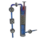
The PUR-D technology is the final purification step, consisting of a distillation column which enables separation/blow-off of non-condensable gasses, thereby reducing O2 content in the final product to max. 5 ppm (v/v) and obtaining corresponding CO2 purity of higher than 99.99% (v/v).
The electrical system for the CO2 generating plant consists of a combined MCC and control panel. From the control panel, which comprises the latest PLC technology, the plant is operated and monitored on a touch color TFT display, ensuring easy and continuous trouble-free operation.
The plant is started by an automatic start sequence and the operation is fully automatic. The entire process is easily surveyed on the operator panel, showing the status of all drives, readings of all transmitters and alarm warnings, which will also be indicated by audible alarm.
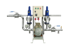
All instruments installed on the skids are wired to junction boxes or remote I/O boxes and tested in our workshop prior to shipment, thus reducing installation and commissioning time on site.
The plants are designed for high efficiency, availability and reliability through components selected for long life and 24/7 operation.
-
PROCESS DESCRIPTION
-
The plant is based on the combustion of fuel in an MEA heater equipped with a burner. After the combustion, the flue gas will have a CO2 content of 10-14% v/v and will exit the MEA heater at a temperature of approximately 250°C.
The flue gas is directed to a flue gas scrubber, in which the gas is cooled and water condensed. Any SO2 present in the flue gas will be removed utilizing a chemical reaction with sodium carbonate (soda ash). The soda ash is automatically added to the scrubbing water through pH control.
After cooling and scrubbing, the gas is led via an exhauster through an absorber, in which the gas flows counter-current to the MEA solution flow. By chemical reaction, the MEA solution absorbs the CO2 from the flue gas. The MEA solution containing the absorbed CO2 (referred to as rich MEA solution) is first pressurised and heated in a heat exchanger and then led to the NOxFlash column. Here most of the contaminants are removed from the rich MEA solution by flashing to the absorber pressure.
Further heating is added to the bottom of the NOxFlash column for further reduction of the contaminants in the MEA solution. This optimises the process yield to the best possible CO2 product without any use of expensive chemicals (Union patent pending).
Afterwards, the rich MEA solution is pumped to a stripper, where the CO2 is released from the MEA solution using the combustion heat generated in the MEA heater. The CO2 depleted MEA solution (referred to as lean MEA solution) is recycled to the absorber. After exiting the top of the stripper, the CO2 rich gas is cooled in a gas cooler and washed in an after-scrubber for removal of potential MEA carry-over. The gas is then compressed in two stages to approx. 15-18 bar(g) by the CO2 compressor.
Prior to liquefaction, the gas is dried to a dew point of approx. -60°C (10 ppm v/v H2O) in the dehydrator. Regeneration is done automatically by electrical heating and the use of dry purge gas from the CO2 condenser. Traces (if any) of acetaldehyde are also removed in the dehydrator. The CO2 gas then passes through an activated carbon filter for the removal of any odour substances.
To remove the last non-condensable gases, the CO2 gas first passes a reboiler in the purification system (type PUR-D). It is then condensed at a temperature of approx. -27°C/-21°C in a
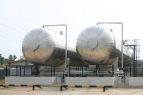
CO2 condenser, where the non-condensed gases are purged off. Finally, the liquefied CO2 is led through the distillation column to an insulated storage tank.
A refrigeration unit, controlled by the CO2 pressure in the CO2 condenser, supplies the matching refrigeration capacity. The liquid CO2 is stored under a pressure of approx. 15-18 bar(g) and a corresponding temperature of approx. -27°C/-21°C. During a non-CO2 production period, the refrigeration unit can operate independently of the rest of the CO2 plant to maintain the correct CO2 storage tank temperature/pressure.
The CO2 produced has a purity higher than 99.99% (v/v) and fulfils quality standards as a food/beverage ingredient.
DOWNLOADS
| Title | Download PDF | |
| Product Leafleft | CO2 Extraction Plants | Download |
| Technical documentation | Looking for operating instructions, installation manual, spare part list etc.? | Please, send us your request |
RELATED PRODUCTS
The Truck Filling Unit is designed for an easy loading and unloading of liquid CO2.
Replaces scrubbing with Potassium Permanganate (PPM) in your CO2 production plant.